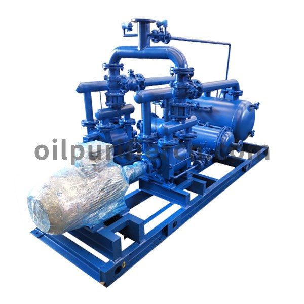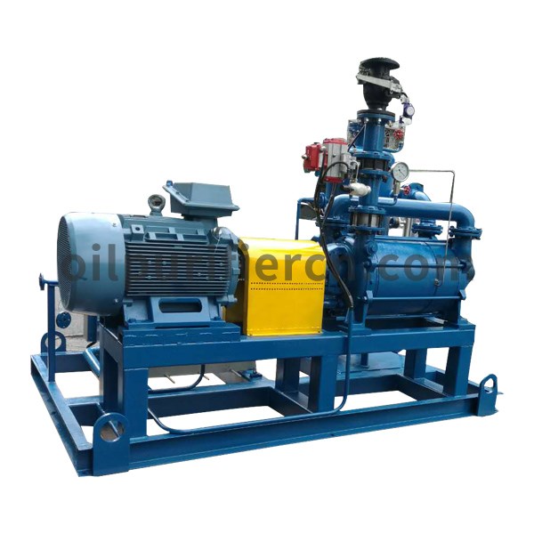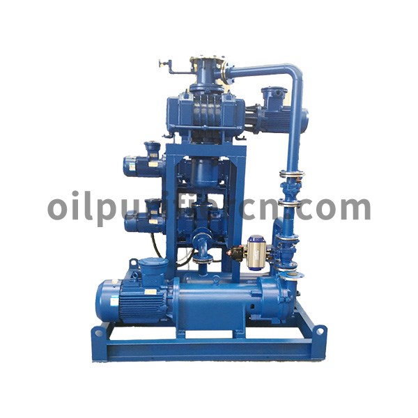
Ⅰ. Water circulation vacuum unit working process
The Water circulation vacuum unit is equipped with an appropriate amount of water in the pump body as a working circulating fluid. When the impeller rotates clockwise in the direction indicated in the figure, water is thrown around by the impeller. Due to the centrifugal force, the water forms a closed ring of approximately equal thickness determined by the shape of the pump cavity. The inner surface of the upper part of the water ring is just tangent to the impeller hub, and the inner surface of the lower part of the water ring is just in contact with the tip of the blade (in fact, the blade has a certain depth of insertion in the water ring).
At this time, a crescent-shaped space is formed between the impeller hub and the water ring, and this space is divided into several small cavities with the same number of blades by the impeller. If the upper part of the impeller is 0 ° as the starting point, the volume of the small cavity changes from small to large when the impeller rotates 180 ° before it is connected to the suction port on the end face. At this time, the gas is sucked in, and when the suction is finished, the small cavity It is isolated from the suction port; when the impeller continues to rotate, the small cavity changes from large to small, so that the gas is compressed; when the small cavity communicates with the exhaust port, the gas is discharged out of the water ring vacuum pump.
Ⅱ. Water circulation vacuum unit technical parameters
Model | Pump models | Pumping speed(L/S) | Ultimate pressure | Gas inlet diameter径(mm) | Gas outlet diameter(mm) | Motor power (kw) | |||||
Main pump | First stage pump | Main pump | First stage pump | ||||||||
Ⅰ | Ⅱ | hPa | Torr | Ⅰ | Ⅱ | ||||||
ZKS150-3 | ZJP-150 | - | 2SK-3 | 150 | 2.7 | 2 | 100 | 50 | 2.2 | - | 7.5 |
ZKS150-1 | ZJP-150 | - | 2SK-6A | 150 | 2.7 | 2 | 100 | 50 | 2.2 | - | 11 |
ZKS300-3 | ZJP-300 | - | 2SK-6A | 300 | 2.7 | 2 | 150 | 50 | 4 | - | 11 |
ZKS150-21 | ZJP-150 | ZJP-70 | 2SK-3 | 150 | 6.7×10⁻¹ | 5×10⁻¹ | 100 | 50 | 2.2 | 1.1 | 7.5 |
ZKS300-21 | ZJP-300 | ZJP-150 | 2SK-6A | 300 | 6.7×10⁻¹ | 5×10⁻¹ | 150 | 50 | 4 | 2.2 | 11 |
ZKS300-41 | ZJP-300 | ZJP-70 | 2SK-3 | 300 | 6.7×10⁻¹ | 5×10⁻¹ | 150 | 50 | 4 | 1.1 | 7.5 |
ZKS600-41 | ZJP-600 | ZJP-150 | 2SK-6A | 600 | 6.7×10⁻¹ | 5×10⁻¹ | 200 | 50 | 7.5 | 2.2 | 11 |
ZKS1200-43 | ZJP-1200 | ZJP-300 | 2SK-6A | 1200 | 6.7×10⁻¹ | 5×10⁻¹ | 250 | 50 | 11 | 4 | 11 |
ZKSY150-3 | ZJP-150 | - | 2YK-3 | 150 | 6.7×10⁻¹ | 5×10⁻¹ | 100 | 50 | 2.2 | - | 7.5 |
ZKSY300-3 | ZJP-300 | - | 2YK-6 | 300 | 6.7×10⁻¹ | 5×10⁻¹ | 150 | 50 | 4 | - | 11 |
ZKSY150-21 | ZJP-150 | ZJP-70 | 2YK-3 | 150 | 5×10⁻³ | 3.8×10⁻³ | 100 | 50 | 2.2 | 1.1 | 7.5 |
ZKSY300-21 | ZJP-300 | ZJP-150 | 2YK-6A | 300 | 2.6×10⁻³ | 2×10⁻³ | 150 | 50 | 4 | 2.2 | 11 |
ZKSY300-41 | ZJP-300 | ZJP-70 | 2YK-3 | 300 | 5×10⁻³ | 3.8×10⁻³ | 150 | 50 | 4 | 1.1 | 7.5 |
ZKSY600-41 | ZJP-600 | ZJP-150 | 2YK-6A | 600 | 2.6×10⁻³ | 2×10⁻² | 200 | 50 | 7.5 | 2.2 | 11 |
ZKSY1200-43 | ZJP-1200 | ZJP-300 | 2YK-6A | 1200 | 2.6×10⁻³ | 2×10⁻² | 250 | 50 | 11 | 4 | 11 |
ZKSS150-1P | ZJP-150 | - | 2SK-6AP | 150 | 4×10⁻¹ | 3×10⁻¹ | 100 | 50 | 2.2 | - | 11 |
ZKSS150-3P | ZJP-150 | - | 2SK-3P | 150 | 4×10⁻¹ | 3×10⁻¹ | 100 | 50 | 2.2 | - | 7.5 |
ZKSS300-3P | ZJP-300 | - | 2SK-6AP | 300 | 4×10⁻¹ | 3×10⁻¹ | 150 | 50 | 4 | - | 11 |
ZKSS150-21P | ZJP-150 | ZJP-70 | 2SK-3P | 150 | 2×10⁻² | 1.5×10⁻² | 100 | 50 | 2.2 | 1.1 | 7.5 |
ZKSS300-21P | ZJP-300 | ZJP-150 | 2SK-6AP | 300 | 2×10⁻² | 1.5×10⁻² | 150 | 50 | 4 | 2.2 | 11 |
ZKSS300-41P | ZJP-300 | ZJP-70 | 2SK-3P | 300 | 2×10⁻² | 1.5×10⁻² | 150 | 50 | 4 | 1.1 | 7.5 |
ZKSS600-41P | ZJP-600 | ZJP-150 | 2SK-6AP | 600 | 2×10⁻² | 1.5×10⁻² | 200 | 50 | 7.5 | 2.2 | 11 |
ZKS1200-41P | ZJP-1200 | ZJP-300 | 2SK-12P | 1200 | 2×10⁻² | 1.5×10⁻² | 250 | 80 | 11 | 4 | 22 |
ZKSS600-21P | ZJP-600 | ZJP-300 | 2SK-12P | 600 | |||||||


